 Knowledge Center
This Gold Phoenix PCB Knowledge Center article compares flex circuits with stiffeners and rigid-flex PCBs, focusing on the functionality, performance, cost and design differences that can affect an early PCB design decision.
When developing a flex PCB-based design, one of the most common early decisions is whether a flex circuit with stiffener(s) will meet the design requirements or whether a rigid-flex construction is necessary or more effective. While there is some overlap between the two approaches, there are significant capability, performance and cost differences that need to be reviewed for a successful design.
Flexible circuits manufactured with stiffeners serve the following functions in a flex PCB design:
Provide mechanical support to specific areas containing SMT and/or PTH components. This prevents the flex circuit from bending at or near components, where bending could compromise solder-joint integrity.
Provide a localized increase in thickness required to meet ZIF connector specifications.
Support heat dissipation.
Stiffeners do not have plated holes and have no electrical interconnect to the circuitry in the flex layers.
For flexible circuit board designs with stiffeners on both sides but in different areas because of component-placement requirements, this adds significant complexity and cost at assembly. Stiffeners on the same side as SMT components will prevent solder paste stencils from lying flat in the SMT areas and may make a rigid-flex construction necessary.
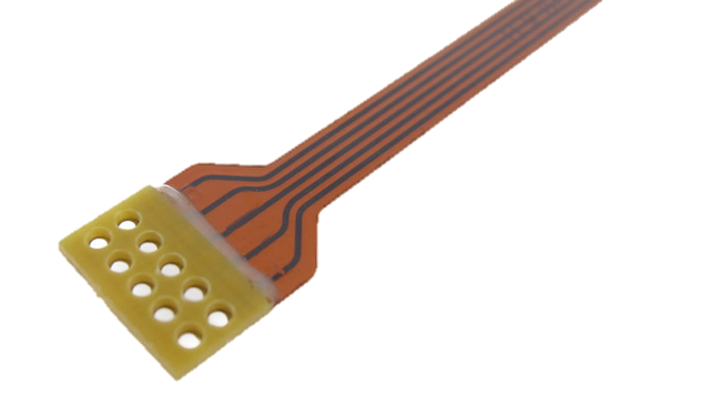
Flexible circuit board designed with stiffeners.
Rigid-flex PCBs provide the same functionality and capability as rigid PCB technology.
They provide fully integrated connections between rigid areas. This eliminates the need for added connectors, reduces board-space requirements and removes additional interconnect points created by connectors. Eliminating these potential points of failure improves design reliability.
They allow SMT components on both sides in the same area or areas.
They can support blind and buried vias.
They allow full-depth PTH holes for higher-reliability PTH component interconnects.
They allow press-fit connectors.
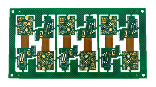
Rigid-flex circuit board designed without stiffeners.
A flexible circuit with stiffeners will, with few exceptions, be more cost-effective at the individual-part level than a comparable rigid-flex PCB. This is due to the additional materials and manufacturing process steps required by rigid-flex technology. The difference can reach 2× or greater.
However, this does not necessarily mean that a rigid-flex solution will be more expensive overall after all additional cost factors are considered. Higher-level integration, reduced component requirements, improved high-speed signal performance and reduced higher-level assembly requirements can make a rigid-flex solution more cost-effective in some designs.
Stiffeners can be incorporated into a flex design to meet a wide variety of requirements:
They can be applied to one or both sides of the design.
They can vary in thickness and material within the same design.
They can be attached with either thermosetting flex adhesive or pressure-sensitive adhesive (PSA). ZIF connector applications require thermoset adhesive.
Silkscreen and PSA are allowed on the external layer of stiffeners.
Electrical shielding layers, if required, cannot extend under stiffeners because of the slip characteristics of the shielding film’s external layer.
Advanced FR4 stiffeners can have circuit layers, but without electrical interconnect to the flex layers.
Common applications include:
Component mounting pads that allow connector mounting lugs to be soldered from both sides for added strength.
SMT pads for edge-mounted connectors.
Additional localized circuit requirements.
One example configuration is a 3-layer flex circuit with FR4 and polyimide stiffeners on both sides.
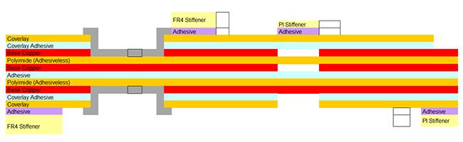
Example of a 3-layer flex circuit with FR4 and polyimide stiffeners on both sides.
The primary advantage of rigid-flex construction is the integration of rigid PCB and flex technology, allowing designs to achieve significantly tighter packaging requirements than other solutions. It can also provide higher performance and reliability by eliminating interconnect points required by connectors and wiring.
Stiffeners are also commonly used in the flex areas of rigid-flex designs and serve the same purposes as in flex-only designs. Designs can incorporate flex sections or tails that terminate in ZIF contacts and therefore require a polyimide stiffener to meet ZIF connector specifications. Flex areas may also contain components that require FR4 stiffeners for support and reliability.
One example configuration is a 6-layer rigid-flex PCB with a 2-layer ZIF flex tail.
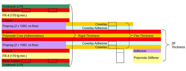
Example of a 6-layer rigid-flex PCB with a 2-layer ZIF flex tail.
Flex circuits with stiffeners and rigid-flex PCBs provide a wide range of design options, and their overlapping capabilities can make the choice difficult early in the design process.
Rigid-flex designs can always meet the capabilities of flex designs with stiffeners, although they often, but not always, carry an unnecessary cost premium. Flex circuits with stiffeners are generally more cost-effective at the individual-part level, but they may introduce additional costs elsewhere in the finished assembly.
Because the best choice depends on the design parameters and overall cost structure, evaluating the available configurations early in the design process can help narrow the options and support more accurate preliminary cost comparisons.
Capabilities
Payment Methods


Specials Price
Carriers


Support Hobbyist
Certificate


Customer Support
Follow Us








