 Knowledge Center
This Gold Phoenix PCB Knowledge Center article compares rigid PCBs and flexible PCBs, including when each type may be appropriate and some of the design and manufacturing considerations that distinguish them.
When the term “PCB” is used, many people think of a rigid printed circuit board. However, a PCB can be either rigid or flexible. Flexible PCBs are commonly known as flex circuits, flex boards, flexible circuit boards or flexible printed circuit boards.
Flex circuits can be shaped, bent, twisted and folded into many configurations. Despite their physical differences, rigid PCBs and flexible PCBs serve the same basic function: connecting electrical and mechanical components together.
Rigid PCBs typically cost less than flex circuits at the individual-board level. However, total cost of ownership can change the comparison. In some applications, flexible PCBs can eliminate components such as connectors, wire harnesses and additional circuit boards.
Removing these components can reduce material cost, labor and assembly cost, and scrap cost.
Many electronic devices, including laptop and desktop computers, audio equipment, solid-state drives (SSDs), flat-screen TVs and monitors, children’s toys and other electronic products, commonly use rigid PCBs. Flex circuits are often used in compact or higher-performance devices such as GPS units, tablets, smartphones, cameras and wearables.
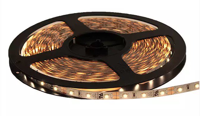
Flex circuits are not limited to highly sophisticated electronics. Simpler applications, such as LED lighting strips, can also benefit from flex circuit technology when flexibility makes installation easier.
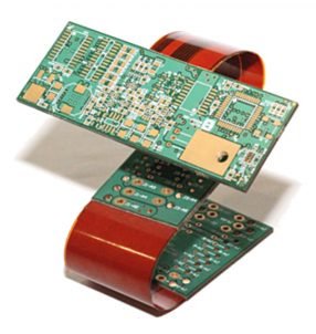
Rigid and flexible circuit sections can also be combined into a unified PCB when the application benefits from both technologies.
Rigid PCB designs must follow design rules such as minimum hole sizes, minimum spacing and trace widths, minimum distances to board edges, copper thickness and overall board thickness. Many of these considerations also apply to flexible PCBs.
Rigid and flexible PCB manufacturing also share several process steps, including drilling and plating holes and vias, photo imaging and development, etching copper traces, pads, outlines and planes, and baking to remove moisture from the PCB.
At this stage of the manufacturing process, the technologies begin to differ: rigid PCBs proceed to the solder mask process, while flex circuits use a coverlay process to protect the external circuitry.
Flex circuit overlay, also known as coverlay, is a lamination process used to encapsulate and protect the external circuitry of a flex circuit. Coverlay serves a purpose similar to solder mask on a rigid PCB, but the coverlay material remains flexible.
A common coverlay construction uses polyimide film coated with a thermoset adhesive. Film thicknesses can range from approximately 0.0005 in to 0.005 in, with 0.001 in and 0.002 in being commonly used thicknesses.
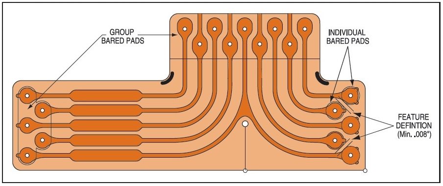
The polyimide and adhesive coverlay is laminated using pressure and heat. Heating allows the adhesive to flow and fill gaps between traces and pads, helping prevent air from becoming trapped between the layers. This adhesive flow also helps achieve complete surface contact and encapsulation.
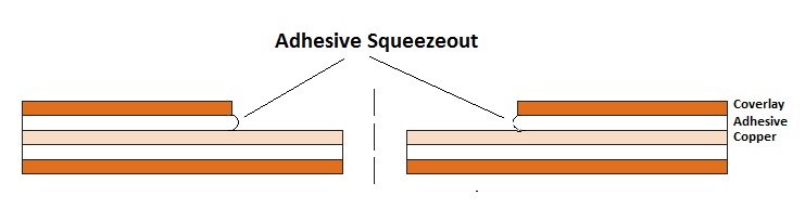
The adhesive may flow slightly beyond the edges of coverlay openings. This is commonly called adhesive squeeze-out and is an expected part of the coverlay lamination process.
After coverlay lamination is complete, component and feature openings can be produced using drilling, routing or laser cutting. Etching is not used to create these openings.
Capabilities
Payment Methods


Specials Price
Carriers


Support Hobbyist
Certificate


Customer Support
Follow Us








